We are hiring! Run with Riesterer and Schnell: Apply Today

We are hiring! Run with Riesterer and Schnell: Apply Today
Search
Choose a Location

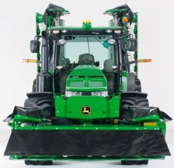 Transport position
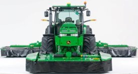 Operating position
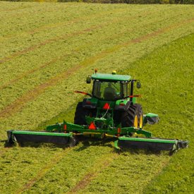
The 388 Twin Rear-Mounted Mower Conditioner is matched with a 131 Front-Mounted Mower-Conditioner to make what is commonly called a Triple-Mounted Mower-Conditioner (TMMC). This combination cuts nearly 8.73 m (28 ft, 8 in.) but can easily be converted to a narrow transport width of 3.1 m (10 ft, 2 in.).
131 Mower-Conditioner transport position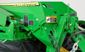 Transport lock for 131 Mower-Conditioner
To prepare for transporting, the side curtains of the 131 Front-Mounted Mower-Conditioner are unlocked and folded into the transport position. This will reduce the overall width during transport. The transport lock lever on the 131 Front-Mounted Mower-Conditioner is engaged so that side-to-side oscillation during transport is eliminated.
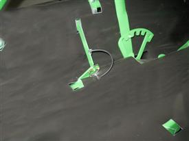 388 Mower-Conditioner side curtain lock
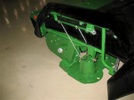 Side curtain support shown in transport position
The side curtains are unlocked and pinned to reduce the overall transport height of the TMMC. The side curtain support provides rigidity to the side curtains during cutting and is folded down in transport to reduce the overall height.
 Zone 2 active
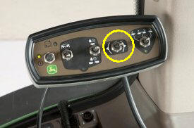
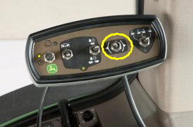 Zone 1 active
Using the control panel configured to headland turn (switch in yellow circle moved to RH, Zone 2 switch centered), the operator uses the tractor hydraulics to raise the platforms. The mower-conditioner frame should be centered in preparation for transport.
Rear three-point hitch may be adjusted, as necessary, to assure the overall height of the mower-conditioner does not exceed 4.0 m (13 ft, 1 in.).
A spring-loaded safety lock secures the mower-conditioner in the raised position.
To prepare for field operation, the rope connected to the safety lock on the 388 Twin Rear-Mounted Mower-Conditioner is held while the platforms are partially lowered (rope can be released as soon as mower-conditioner is unlatched), using the control panel and tractor SCV.
The balance of the procedure above is reversed to continue on to field operation.
 Left-hand accumulator pressure gauge
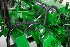
 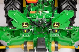 Right-hand and left-hand accumulators
Flotation is controlled by accumulators on both the right-hand and left-hand cutting platforms. The easy to read gauges (one for each cutting platform) enable the operator to easily adjust the float pressure to the desired level.
A ball valve by the pressure gauge is opened and by using the control panel mounted in the tractor and the tractor selective control valve (SCV), the pressure can be adjusted to meet varying ground or crop conditions.
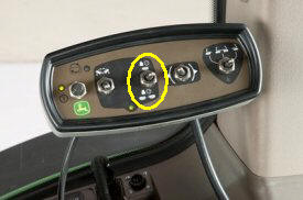 Control for adjusting flotation (yellow circle)
The control panel is used to adjust flotation of both the rear cutting platforms as well as the 131 Front-Mounted Mower-Conditioner.
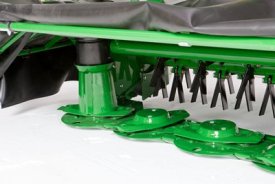
 Impeller conditioner
Each cutting unit is equipped with 54 free-swinging, steel impeller tines. This John Deere conditioner provides excellent conditioning performance and fluffy windrows.
Impeller conditioning is standard equipment on all John Deere mower-conditioners.
Proper conditioning in a wide range of crops can be achieved when the conditioner is properly adjusted.
The impeller conditioner works well in legumes, especially alfalfa and most all-grass crops. Impeller conditioners are not recommended for thick-stemmed or cane-type crops, such as sudan or sudex, or crops over 5-ft tall.
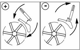 Impeller conditioning
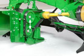 Adjusting impeller speed (shield removed for illustration)
The speed at which the tines rotate will also affect the degree of conditioning. Two impeller speeds can be achieved by interchanging the upper sheave and the lower sheave.
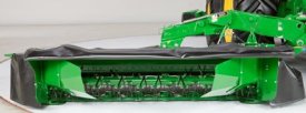
 Windrows to match your needs
Forming shields are easily adjusted to control material flow. This allows the operator to match the windrow width to harvesting requirements.
 Windrow forming shields (rear curtain raised for visibility)
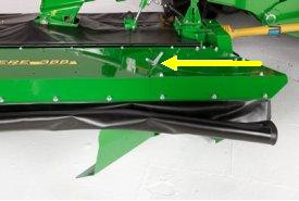 Adjustment handle (arrow)
The forming shields are easily adjusted to match harvest requirements. No tools are required to adjust the forming shields. Windrow width on each unit can be adjusted from 1.2 to 2.5 m (3 ft, 11 in. to 8 ft, 2 in.).
A widespread kit is available as a field-installed bundle. The bundle consists of vanes that are installed behind the conditioning hood. The windrow width when using the widespread kit can be adjusted to be approximately the same as the cutting width of the platform.
 388 Twin Rear-Mounted Mower-Conditioner
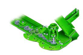 Cutterbar cutaway drawing
Power is transmitted from the 1000-rpm tractor (1-3/4-in.) PTO through a central gearcase to the twin rear-mounted cutterbars.
 Control panel
The simple to operate control panel enables the operator to easily operate all of the hydraulic functions of the 388 Twin Rear-Mounted Mower-Conditioner.
Features/functions of the control panel include:
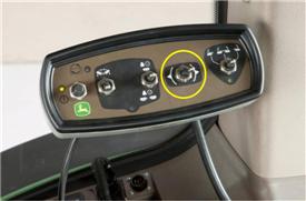 Control panel zone selection
With the power switch on, the zone selector switch (yellow circle) determines which functions are active by powering either Zone 1 or Zone 2.
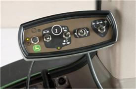 Zone 1 active
With the zone selector switch moved to activate Zone 1 the operator can fold the 388 Twin Rear-Mounted Mower-Conditioner into transport position or adjust the cutterbar flotation on either the front or rear cutterbars.
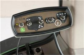 Zone 2 active
Zone 2 is the primary setting for field operation. The three-position switch in Zone 2 is used to select the headland turn or working position of the rear cutting units. The position of the switch will determine which cutting platform or both will be raised
| Power requirements | 388-rear-mount-mower-conditioner Current Model |
|---|---|
| PTO speed | 1,000 rpm |
| HP 540 rpm PTO | |
| HP 1000 rpm 1-3/8 in. PTO | |
| HP 1000 rpm 1-3/4 in. PTO | With 131 Front-Mounted Mower-Conditioner: 147 kW 190 hp |
| Powerline type | |
| Hydraulic pressure required | |
| Cutterbar | |
| Type | Rotary |
| Cutting width | With 131 Front Mounted Mower-Conditioner: 8.7 m 28.6 ft |
| Cutting height | 3-8 cm 1.2-3.2 in. |
| Number of disks | 8 per unit |
| Number of knives | 16 per unit |
| Disk speed | 2,986 rpm |
| Knife tip speed | |
| Disk drive | Gear |
| Lubrication | GL-5 gear lubricant |
| Oil reservoir capacity | 2.25 L 0.59 U.S. gal. |
| Cutterbar oil check | Fill plug |
| Cutterbar angle | Adjustable |
| Angle adjustment | Tractor center link |
| Angle range | |
| Cutterbar protection | Shear shaft |
| Adjustable gauge shoes | |
| Conditioner | |
| Impeller | Width 264 cm 104 in.Number of V-tines 54 per unitNumber of speeds TwoDrive Belt and sheavesConditioner hood Adjustable |
| Rolls | |
| Tractor hookup | |
| Standard hitch | Tractor 3-point |
| Ball joint equal angle hitch | |
| Rockshaft swivel hitch | |
| Drawbar swivel hitch | |
| Dimensions | |
| Overall width | Transport 3.1 m 10.1 ft |
| Overall length | |
| Weight | With impeller conditioner 2,986 kg 6,583 lb |
| Standard tires | |
| General | |
