We are hiring! Run with Riesterer and Schnell: Apply Today

We are hiring! Run with Riesterer and Schnell: Apply Today
Search
Choose a Location

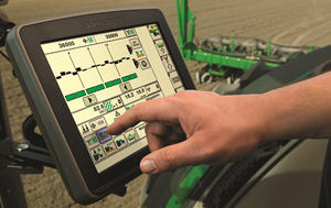 SeedStar XP shown on the GreenStar™ 3 2630 Display
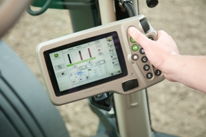 SeedStar XP shown on the GreenStar 2 1800 Display
Building upon the foundation of SeedStar 2, the SeedStar XP system takes planter monitoring to the next level. SeedStar XP is compatible with the GreenStar 2 1800 and 2600 Displays, GreenStar 3 2630 Display, the Gen 4 4200 CommandCenter™ Display, the Gen 4 4600 CommandCenter Display, the 4240 Universal Display, and the 4640 Universal Display. SeedStar XP is not compatible with the Gen 4 Extended Monitor.
Specific information about how the planter is performing enables the operator to make needed adjustments for implement optimization.
The SeedStar XP planting functions are fully integrated with the full spectrum of Precision Ag Technology applications such as Swath Control Pro™ system for planters, GreenStar AutoTrac™ assisted steering system, John Deere Operations Center, Documentation, and others. Integrated planting technologies for better asset utilization and ease of use is just part of what SeedStar XP provides.
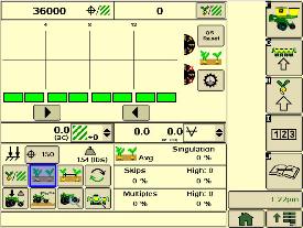 SeedStar XP seed singulation planter run page
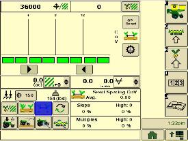
Understanding the meter singulation performance on the planter is critical to minimizing the amount of seed multiples and skips. As a result, the SeedStar XP monitoring system provides real-time information from the row-units about the overall seed singulation performance.
As seen in the screen shot image above, seed multiple information is displayed on the top portion of the planter-at-a-glance bar with seed skip information on the lower portion. This provides the operator a better understanding of relative seed multiple and skip data on a row-unit basis, all within one easy glance.
Also, within the seed singulation planter run page, information about row-units with the highest percentage of seed multiples and skips is provided in order to make necessary adjustments for better planter optimization.
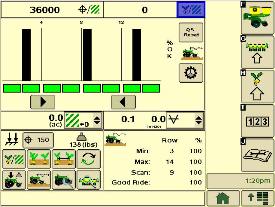 SeedStar XP ride dynamics planter run page
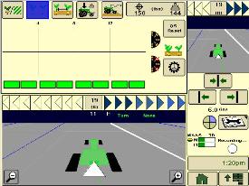
While operating a planter, travel speed and field conditions can affect the amount of row-unit bounce that is experienced. Excessive row-unit bounce or vertical motion can cause problems with meter performance. To better understand the amount of row-unit vertical motion when travelling through a field, the SeedStar XP monitoring system provides real-time information on row-unit ride dynamics.
As seen in the ride dynamics planter-at-a-glance screen shot image above, the SeedStar XP system provides ride dynamic information for each sensor node that is mounted on the planter. Each sensor node transmits ride dynamic information for each planter frame section to allow for the operator to make necessary operating adjustments to improve overall planting performance.
 SeedStar XP downforce planter run page
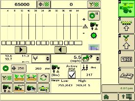
As row-unit downforce systems gradually change from heavy-duty downforce springs to pneumatic downforce, being able to understand the amount of as-applied row-unit downforce is needed while operating the planter.
With various soil conditions, moisture, etc. experienced while planting, it is imperative to have the ability to change actual row-unit downforce to have enough force for the Tru-Vee openers to penetrate the soil media. However, in some conditions, having too much downforce applied to the row-units for effective opener penetration could cause problems with side wall compaction from the gauge wheel.
Side wall compaction within the seed furrow can cause hatchet roots to develop, or roots that do not have the ability to penetrate the seed furrow soil media. This could lead to poor plant emergence and eventually lower overall yield performance.
With the SeedStar XP monitoring system, row-unit downforce information is measured by the downforce sensor and sensor nodes and transmitted to the GreenStar 2 Display in the tractor cab (as seen in the image above). The row-unit downforce information is displayed on the top portion of the planter-at-a-glance bar with more row-unit downforce information on the lower portion.
Two different control options are available on 1775NT, 1795, and DB Series Planters for pneumatic downforce. The base pneumatic downforce system requires manual control of the downforce to maintain the desired planting results or row-unit margin. Optional active pneumatic downforce takes SeedStar XP even further by removing constant downforce adjustments from the operator and actively controlling the downforce system to maintain a desired target margin.
 SeedStar XP seed spacing planter run page
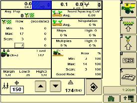
Throughout the planting process, obtaining good seed spacing is critical toward achieving plant growing conditions for maximum yield potential.
Today, many items are adjusted on the planter prior to planting to optimize overall seed spacing performance. After such adjustments are made, information about the actual seed spacing performance during planting was missing within the planter monitoring system. Now with SeedStar XP, seed spacing information is transmitted live via the GreenStar display to show the operator exactly what is happening with the planter behind them.
The SeedStar XP transmits seed spacing information onto the planter-at-a-glance bar for easy understanding of planter seed spacing performance. Also, information about seed skips and multiples is provided to help understand actual planter meter performance and other related system functions in order to make necessary adjustments if needed.
NOTE: Seed spacing and seed singulation information is only available when planting crops with seed drop rates below 40 seeds per second such as corn. With higher population crops such as soybeans the system does not provide spacing and singulation information because the number of seeds dropping per second is much higher.
 SeedStar XP planter details
 With the capability of monitoring differences in planting performance items such as seed singulation and row-unit downforce, having one screen to view all planter performance elements is needed to understand the whole planting system. SeedStar XP combines all of the various planting performance elements into one full-color, planter overview screen to enable for a quick understanding of relative planting functionality.
 SeedStar XP seed singulation half screen
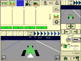 SeedStar XP seed spacing half screen
Other SeedStar XP monitoring features include:
SeedStar XP retains all of those SeedStar 2 features that producers value and have come to expect:
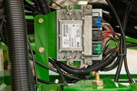
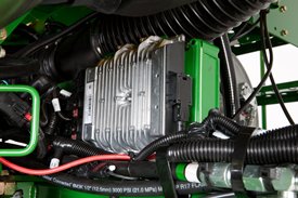 Planter main 2 controller
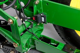 Sensor node assembly installed
The SeedStar XP monitoring system contains the following components in order to support the planting data transfer to the GreenStar 2 Displays:
The planter main 2 controller processes the row-unit data from the sensor node assemblies located on the row-unit head casting. The processed information is then sent to the SMVR controller to be integrated into the displayed information being sent to the GreenStar Display.
Downforce sensor assemblies are found on row-units with sensor nodes installed. The downforce sensor assembly is assembled with the gauge wheel depth-adjustment handle and provides gauge wheel pressure information to the respective sensor node for data processing.
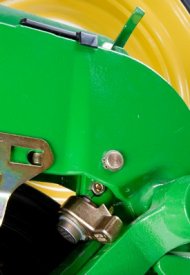 Downforce sensor installed
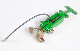 Downforce sensor assembly
Depending on the planter size, different configurations of sensor nodes and downforce sensors are installed in support of the SeedStar XP monitoring system.
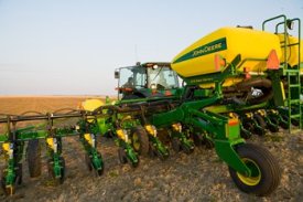 1720 CCS with 3523.9 L (100 bu) of seed capacity
Central Commodity System (CCS) seed delivery adds productivity through increased seed capacity, bulk-fill capability, and easy, thorough cleanout. The two tanks have a combined capacity of 3523.9 L (100 bu) on the 1720 CCS Planters.
The 1720 CCS Planters have been designed to allow for a convenient central filling location and easy cleanout. The rear entry ladder provides access to the filling platform between the tanks.
For those who work into the night, a fill light package is standard on machines equipped with CCS.
If the seed-carrying vehicle requires hydraulic power to run the unloading system, the auxiliary hydraulic coupler option can be ordered. These couplers are located at the bottom of the staircase and can be coupled under pressure. The system has a separate system filter that ensures the planter's hydraulic system remains free of contaminates.
The following crops can be planted with CCS: corn, sweet corn, popcorn, cotton, sunflowers, soybeans, and sorghum (milo).
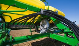 1720 CCS fan and seed delivery hoses
CCS is about reducing the time spent filling the planter with seed while maximizing the time spent planting. CCS for planters is a form of seed handling and delivery. The row-units perform the final task of seed metering and placement.
The CCS seed delivery process relies on a hydraulically driven fan to move seed from the CCS tanks to the row-units. A flow control valve and gauge, located near the tank, allows for the proper tank pressure setting based on seed type.
Air from the fan pressurizes the CCS tanks and delivers seed to the seed hoppers. Air flow enters the seed tanks through a nozzle in the manifold which pressurizes the tank. The air then picks up seed and moves out the other end of the nozzle into the seed delivery hoses. These hoses route the seed toward the hopper. A small amount of seed is traveling in the delivery hoses only when needed.
The hopper fills with seed until the delivery hose (discharge elbow) is covered. Once the opening is restricted, seed flow through the hose stops. Air flowing to the row-unit travels into the hopper and out through a vent. As the seed is picked up by the meter and planted, the seed pool shrinks until the end of the delivery hose is uncovered. At that time, the air flow and seed delivery resume, and the seed pool in the hopper is replenished.
Seed cleanout could not be easier with a CCS planter. Whether there are 12 or 48 rows, the CCS system and Pro-Series XP™ row-units make quick work of this chore. When the operator is finished planting, any remaining seed can simply be removed via access doors at the bottom of the CCS tank.
Because seed is only traveling through the CCS delivery hoses when required by the meter, there is not much left to clean.
Next, CCS seed delivery hoses are purged with air from the CCS fan, and the excess seed is pushed to the individual meters.
Lastly, the vacuum meter door is opened, and seed is removed with the supplied catch pan.
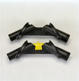 Manifold nozzle and nozzle with cover installed
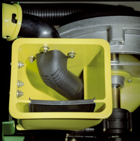 Small-seed elbow installed in mini-hopper
CCS seed delivery system increases planting productivity across the seven approved crops listed above. While highly effective when delivering seed from the CCS tanks to the vacuum meters, small or light seeds (sorghum and small cotton) will require two additional components to aid in proper seed delivery.
Manifold nozzle covers (clips) should be installed to ensure seed is adequately picked up into the air stream for delivery to the row-unit. Mini-hopper discharge elbows should also be changed from the standard elbow (holes) to the small seed elbow (slotted openings) when planting sorghum (milo) and small cotton.
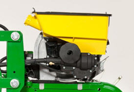
 Variable-rate drive system
The seed variable-rate drive on 1720 CCS Planters provides the ultimate planting productivity by utilizing three hydraulic motors to turn the seeding drive shaft. Hydraulic control of the seeding drive allows for on-the-go seeding rate changes right from the display mounted inside the tractor cab. Combine this seeding flexibility with the map-based planting option and seeding rates adjust automatically based on a prescription map.
Seed variable-rate drive requires the SeedStar™ monitoring system and a speed input signal. Either tractor or planter radar may be used or a global positioning system (GPS) speed signal. Radar speed input signal is recommended. Planter radar is ordered separately.
Seed variable-rate drive offers the following advantages:
 Three-width drive disconnect control
Three-width drive disconnect is base equipment on the 1720 CCS Planters. This feature is activated by three individual console mounted switches (control box) conveniently located in the tractor cab. The function easily shuts off the planter row-unit seed meters by one-, two- or three-drive segments independently.
 RowCommand on a MaxEmerge™ 5 row-unit
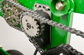 RowCommand on a chain drive MaxEmerge 5 row-unit
Controlling input costs and improving productivity are key producer requirements today. RowCommand is an effective, integrated John Deere solution designed to meet these intensifying needs. The RowCommand system manages seed output, reduces yield drag, and improves harvest capabilities on all Pro-Shaft™ driven row-units, and chain-driven MaxEmerge 5.
NOTE: Chain-drive RowCommand is only compatible with planters equipped with pneumatic downforce systems. On planters equipped with the heavy-duty downforce springs, potential chain interference may result and is not recommended.
NOTE: Chain-drive RowCommand requires some modification to brackets in order to function with corn finger pickup meters.
NOTE: Pro-Shaft drive RowCommand is compatible on MaxEmerge 5 row-units with vacuum and corn finger pickup meters. For mini-hopper row-units, RowCommand is compatible on vacuum meters only and is not compatible on corn finger pickup meters. Pro-Series™ XP row-units with corn finger pickup meters are not compatible with RowCommand.
RowCommand controls seed output by incorporating individual, low amperage clutches inside the Pro-Shaft and chain-driven gearboxes. Clutches are completely enclosed within the gearbox housing to protect them from the elements and harsh operating conditions.
When power is supplied, either manually or through John Deere Section Control software, clutches disengage the seed meters and seed flow stops. Controlling seed output at individual rows reduces overplanting in point rows and maximizes seed placement when entering/exiting headlands.
 Electronic power modules shown on a 1775NT Planter
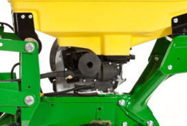 RowCommand clutch on MaxEmerge 5 with 105.7-L (3-bu) hopper
RowCommand is a simple and efficient solution to control individual row planting. This system does not utilize air to operate; therefore, no compressor, air lines, or valve modules are required.
RowCommand utilizes low-voltage controller area network (CAN) messaging to signal power to the desired clutches to stop planting or eliminates power to resume planting.
This means very little power is used in normal planting conditions, and in the event a clutch fails electrically, the meter will continue to plant.
The RowCommand system requires the following five basic components to operate:
Clutches are protected within the sealed Pro-Shaft and chain-driven gearboxes for years of trouble-free operation and simple installation or removal. RowCommand has true individual-row control of up to 16 clutches or sections for planters larger than 16 rows.
Unique to RowCommand, the 16 available control sections can be configured based on operator preferences. For example, on a 1775NT 24-Row Planter, every two rows can be paired together for a total of 12 control sections, or control the outermost eight rows individually and the remaining inner rows paired together for 16 control sections.
While SeedStar with RowCommand has 16 control sections, a minimum of 152.4-cm (60-in.) wide sections are recommended for optimum Swath Control Pro™ solution capabilities. As with other Swath Control Pro products, an SF2 signal is the minimum level of accuracy recommend for operation.
RowCommand is available as a factory-installed option or as an attachment for field conversion attachments for the following Pro-Shaft drive planter models (see chart below).
| Planter model | Row configuration |
| 1725 | 12-row narrow, 12-row wide, and 16-row narrow |
| 1725 Central Commodity System (CCS™) | 16-row narrow |
| 1765 | 12-row narrow |
| 1775 | 12-row narrow |
| 1775NT | 12 row, 16 row, and 24-row narrow |
| 1775NT CCS | 12 row, 16 row, and 24-row narrow |
| 1795 | 12/23 row, 12/24 row, 16/31 row, and 16/32 row |
| 1795 | 24 row, 50.8 cm (20 in.) |
| DB 44 | 24 row, 55.9 cm (22 in.) |
| DB 58 | 32 row, 55.9 cm (22 in.) |
| DB 60 | 36 row, 50.8 cm (20 in.) or 47 row, 38.1 cm (15 in.) |
| DB 66 | 36 row, 55.9 cm (22 in.) |
| DB 80 | 32 row, 76.2 cm (30 in.) or 48 row, 50.8 cm (20 in.) |
| DB 88 | 48 row, 55.9 cm (22 in.) |
| DB 90 | 36 row, 76.2 cm (30 in.) |
| DB 120 | 48 row, 76.2 cm (30 in.) |
| DR (Deere/Orthman™ planter) 16R40 | 16 row, 101.6 cm (40 in.) |
| DR (Deere/Orthman) 18R38 | 18 row, 96.5 cm (38 in.) |
In terms of planter compatibility, RowCommand for chain drive is designed for the following planter model configurations equipped with pneumatic downforce systems.
| Planter model | Row configuration |
| 1725 | 12-row narrow, 12-row wide, and 16-row narrow |
| 1765 | 12-row narrow |
| 1775 | 12-row narrow |
| 1775NT | 12 row and 16 row |
| 1775NT CCS | 12 row and 16 row |
| DB 44 | 24 row, 55.9 cm (22 in.) |
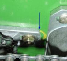
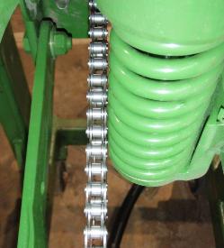 Chain interference with heavy-duty downforce
As seen in the image, chain interference may result when operating chain-drive RowCommand on planters equipped with short and long parallel arms and heavy-duty downforce springs.
NOTE: Chain-drive RowCommand is only compatible with planters equipped with pneumatic downforce systems. On planters equipped with the heavy-duty downforce springs, potential chain interference may result and is not recommended.
 Bracket material removal
Due to the design characteristics of the chain-drive RowCommand clutch, some modification to the corn finger pickup meter drive bracket is required. As seen in the picture to the left, some material needs to be removed from the front of the meter drive bracket in order for the chain-drive RowCommand clutch to have sufficient space for installation.
NOTE: Chain-drive RowCommand requires some modification to brackets in order to function with corn finger pickup meters.
To add RowCommand to a model year 2009 and newer planter model listed above is simple. Pro-Shaft drive attachments for field conversion and chain-drive attachments for field conversion are available by planter model to add the appropriate number of clutches, EPMs, brackets, hardware and row-unit harnesses. For complete installation and part detail for the RowCommand conversion, please use the RowCommand compatibility tool per specific planter model.
RowCommand is compatible and available for model year 2003 (serial number 700101) to 2008 (725101) planter models listed above. In addition to the attachment for field conversion attachment, a planter mainframe harness, SeedStar 2 controller (wedge box), and additional CAN harnesses are needed.
Coupling RowCommand with Swath Control Pro provides the ultimate in precision planting and productivity. One company, one integrated solution are what we offer by incorporating Swath Control Pro capabilities within the SeedStar 2 wedge box (controller). Unlike previous systems, no rate controller, additional harnessing, or components are required to achieve automated individual-row control.
SeedStar 2 monitoring, RowCommand, and Swath Control Pro activation from John Deere Precision Ag Technologies are all that is needed when ordering.
RowCommand is a simple and efficient means to control individual row planting through the use of low-voltage electric clutches. When activated, each clutch consumes no more than 0.5 amps. By design, power is only supplied to the clutch when a signal is received to stop planting. In a normal planting condition, no power is supplied and the clutch is de-energized.
Power for the RowCommand system is provided from the 9-pin ISO implement connector. All late-model 8X00 and 9X00 Series John Deere Tractors equipped with the 9-pin ISO implement connector are capable of supplying ample power for system operation.
Along with ample system power, a GreenStar display and SeedStar monitoring are required for operation and control interface. The GreenStar display is where system setup, control settings, and manual control functions are performed.
 Hydraulic steering cylinder
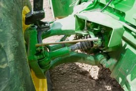 Position sensor
The hydraulic steering assists the operator while backing into the next pass. The implement wheels are steered in the opposite direction of the tractor steering wheels when in reverse. The system is calibrated to steer the lift-assist wheels to the ideal steering angle when turning in reverse and guides the planter from a position sensor mounted to the tractor's front axle.
This steering system prevents the lift-assist wheels from casting or spinning around when the direction is changed from forward to reserve. This saves disruption to beds or soil. The hydraulic steering also provides resistance to lift-assist wheels, eliminating vibrations from the wheels while traveling forward, and is most beneficial during transport.
 Less hydraulic steering
Less lift-assist wheel steering is available to producers who do not need to guide the lift-assist wheels in reverse. This eliminates the need for the position sensor mounted the tractor’s front axle. The less hydraulic steering option does not provide resistance to vibrations from the lift-assist wheels during transport and allows the wheels to caster or spin around during direction changes.
| Key Specs | 1725-ccs-twin-row-planter Current Model |
|---|---|
| Number of rows | 12x2 Twin Row |
| Row spacing | 91.4 or 96.5 cm 36 or 38 in. |
| Frame - Fold configuration | Stack-folding |
| Frame - Flexibility | Up: 10 degree (angle) Down: 7 degree (angle) |
| Row unit seed hoppers | Mini-Hoppers |
| Seed Meters | Base Vacuum |
| Rows and Row Spacing | |
| Number of rows | 12x2 Twin Row |
| Row spacing | 91.4 or 96.5 cm 36 or 38 in. |
| Frame | |
| Fold configuration | Stack-folding |
| Frame tube size | |
| Fold-and-go from tractor cab | |
| Flexibility | Up: 10 degree (angle) Down: 7 degree (angle) |
| Hitch | |
| Base | |
| Optional | |
| Rear hitch | |
| Lift System | |
| Type | Semi-integral only |
| Number of cylinders | |
| Tires | |
| Base | 12.5L-15SL 20 ply implement: 303 kPa 3.0 bar (44 psi) 7.60-15 8 ply implement: 359 kPa 3.6 bar (52 psi) 7.6-15 6 ply - traction: 276 kPa 2.8 bar (40 psi) |
| Optional | |
| Quantity | |
| Row Units | |
| Type | ExactEmerge™ row units MaxEmerge™ 5 row units or MaxEmerge 5e row units |
| Opener | Tru-Vee Double Disk |
| Depth gauging | |
| Adjustment | |
| Walking wheels | |
| Row unit seed hoppers | Mini-Hoppers |
| Row unit down force | Adjustable heavy-duty ---- |
| Scrapers, opener blades | |
| Seed tube sensors | |
| Seed Meters | |
| Base | Vaccum |
| Optional | |
| Finger pickup | |
| Radial bean meter | |
| Central Commodity System | Seed capacity Two CCS™ bulk tanks each with capacity of: 1762 L 50 bu |
| Drive System | |
| Base | 56 V electric drive |
| Optional | |
| Number of drive wheels | |
| Drive wheel disconnect | |
| Counter shaft | |
| Drill shaft | |
| Seed transmission | |
| Transmission combinations | |
| Markers | |
| Type | |
| Control | |
| Marker disk | |
| Shear bolt protection | |
| Less marker option | |
| Closing System | |
| Rubber tire closing system | |
| Cast iron closing system | |
| Herbicide and Insecticide | |
| Insecticide only hopper | |
| Herbicide only hopper | |
| Insecticide and herbicide hopper | |
| Liquid Insecticide System | |
| System available | |
| Tank capacity | |
| Seed Monitor System | |
| Base | SeedStar™ electronic system |
| Optional | |
| Tillage Attachments | |
| Unit-mounted coulter | |
| Frame-mounted coulter | |
| Bubble blade | |
| .63-in. fluted blade (25 flutes) | |
| .7-in. fluted blade (13 flutes) | |
| 1-in. fluted blade (8 flutes) | |
| Row tillage support hanger | |
| Tine tooth | |
| Cons. furrower w/ leading cutout blade | |
| V-wing bed sweeps | |
| Row cleaner | |
| Row cleaner - unit-mounted coulter | |
| Row cleaner - unit-mounted DD fert. opener | |
| Fertilizer | |
| Onboard / towed / tractor tanks | |
| Tank capacity | |
| Fixed-rate application | |
| Variable-rate application | |
| Pump type | |
| Pump rate | |
| Fertilizer opener type | |
| Flow divider distribution system | |
| Pressure manifold distribution system | |
| Dry fertilizer | |
| Dimensions | |
| Transport width (with markers) | |
| Transport width (without markers) | |
| Transport length | |
| Transport height | |
| Transport weight | |
| Transport underframe clearance | |
| Field operation width | |
| Field operation length | |
| Ag Management Solutions | |
| Map-based seeding | |
| Field documentation | |
| Parallel tracking | |
| Additional Information | |
| Recommended tractor horsepower | Vaccum system hydraulic drive: horsepower required: 4.5-10.4 kW 6-14 hp Minimum tractor size: 201 kW 270 hp Tractor recommendation: Currrent model (minimum) 8430 MFWD with dual rear tires and 20 front weights. |
| Recommended tractor hydraulics | Hydraulic oil required to operate the planter: 227 L/min 60 gpm Hydraulic system standby pressure: 15,513 kPa 155 bar (2250 psi) Hydraulic system working pressure: 20,684 kPa 207 bar (3000 psi) Hydraulic system burst pressure: 82,737 kPa 827 bar (12,000 psi) |
| Warranty length | |
| Date collected |
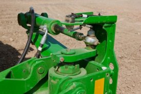
 Auxiliary hydraulic outlet bundle
A set of ISO hydraulic couplers is available as an attachment for 1720 CCS™, 1770NT CCS, 1790 Planters. They can also be installed on the 16row40 and 18row38 custom integral planters. Couplers are intended to be used with an auger to fill the CCS tanks with seed.
Couplers are located on the stairway to the CCS tank platform.
System will hook up under pressure. The system utilizes a push/pull knob for on/off operation.
A 25-micron filter is included with the system. Oil is from the planter CCS fan circuit and contamination must be kept to a minimum.
